 | 101781 | Other by www.smart-prototyping.com")
 | 101781 | Other by www.smart-prototyping.com")
 | 101781 | Other by www.smart-prototyping.com")
 | 101781 | Other by www.smart-prototyping.com")

Description
A20 is a wireless module that combine GPRS and WiFi, also it supports camera connection. It uses ESPRESSIF’s WiFi IC ESP8285 for the WiFi function.
A20’s GPRS module and WiFi module can work separately, be powered separately. This is a good solution for your IoT device to connect internet all the time no matter where it is.
You can choose the following working model to suit your project:
- Only GPRS. For this model, only provide power for GPRS part, then use MCU to control the GPRS by serial port.
- Only WiFi. Just like the only GPRS, only provide power for WiFi part, use MCU to control WiFi by serial port.
- WiFi and GPRS. Use 2 serial port to control WiFi and GPRS separately.
- WiFi as MCU to control GPRS. Under this model, you can use WiFi IC ESP8285 as MCU to control GPRS. Because there is only one two-way serial port, so user need to program ESP8285.
Pin map
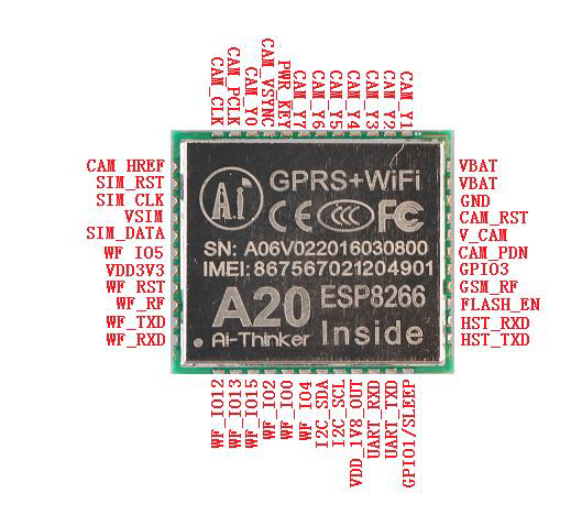
Pin Number | Pin name | Explanation |
1 | CAM_Y1 | Camera data Y1 |
2 | CAM_Y2 | Camera data Y2 |
3 | CAM_Y3 | Camera data Y3 |
4 | CAM_Y4 | Camera data Y4 |
5 | CAM_Y5 | Camera data Y5 |
6 | CAM_Y6 | Camera data Y6 |
7 | CAM_Y7 | Camera data Y7 |
8 | PWR_KEY | Power, keep >1.9V for 2 secs the camera will power on, after that keep it on or off, the camera will continue, this pin only requires voltage, no need real power supply. |
9 | CAM_VSYNC | Camera VSync pin |
10 | CAM_Y0 | Camera data pin Y0 |
11 | CAM_PCLK | Camera PCLK |
12 | CAM_CLK | Camera clock |
13 | CAM_HREF | Camera href |
14 | SIM_RST | Sim card RST |
15 | SIM_CLK | SIM Card clock pin |
16 | VSIM | SIM power VCC |
17 | SIM_DATA | SIM data |
18 | WF_IO5 | ESP8285 GPIO5 |
19 | VDD3V3 | ESP8285 3.3V main power |
20 | WF_RST | ESP8285 reset |
21 | WF_RF | ESP8285 RF |
22 | WF_TXD | ESP8285 UART0 TXD |
23 | WF_RXD | ESP8285 UART0 RXD |
24 | WF_IO12 | ESP8285 GPIO12 |
25 | WF_IO13 | ESP8285 GPIO13 |
26 | WF_IO15 | ESP8285 GPIO15 |
27 | WF_IO2 | ESP8285 GPIO2 |
28 | WF_IO0 | ESP8285 GPIO0 |
29 | WF_IO4 | ESP8285 GPIO4 |
30 | I2C_SDA | Camera IC I2C DATA |
31 | I2C_SCL | Camera IC I2C CLOCK |
32 | VDD_1V8_OUT | OUTPUT 1.8V, can connect to camera IC 1.8V |
33 | UART_RXD | AT serial port RXD, 2.8V |
34 | UART_TXD | AT serial port TXD, 2.8V |
35 | GPIO1/SLEEP | Control sleep model, high level off, low level on. Under sleep model, current<1mA, and serial port is unavailable. Phone call, SMS, GPRS can wake the module from sleep model. |
36 | HST_TXD | Download serial port TXD, 2.8V |
37 | HST_RXD | Download serial port RXD, 2.8V |
38 | FLASH_EN | Flash light control pin, normally need additional amplifier circuit to power the LED light. |
39 | GSM_RF | GSM RF antenna pin, it requires 50 Ohm impedance when you design PCB |
40 | GPIO3 | Normal GPIO pin, when there is call, SMS, GPRS data in, the module will automatically awake, this pin will output single, from high level to low level, falling edge trigger. |
41 | CAM_PDN | Camera power down |
42 | V_CAM | Camera main power |
43 | CAM_RST | Camera reset |
44 | GND | GND |
45 | VBAT | Outside power in 3.5v-4.2v, the power supply’s maximum output current must higher than 2A, otherwise the module cannot work stably. This pin also relates to some GPRS/GSM VCC. |
46 | VBAT |
Tips:
- The camera port only support 0.3M pixel fix-focus camera. Support IC including OV7670, GC0328, GC0309. If you want to use other camera, you can contact us or the manufacturer for software support.
- In the pin list, the red font pins are all for WiFi, the rest is all for GPRS.
- GPRS At serial port default speed is 115200.
Datasheet