
")
How to start with PsyFi32 (Windows tutorial)
In this tutorial you will learn how to use the amazing development board PsyFi32 with the Arduino IDE. If you don't have one, here is the product link.
For all of the ESP32 based development board, there isn’t an official Arduino board manager install yet so you have to follow these steps to get started :
Before starting the installation you need to download the updated version of the Silicon Labs CP210x USB to UART Bridge VCP Drivers.
Go to this link and choose the right version for your OS.
https://www.silabs.com/products/development-tools/software/usb-to-uart-bridge-vcp-drivers
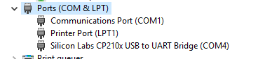
How to verify the driver is installed correctly? You can first plugin in the PsyFi32 board to your computer, and go to your computer’s device manager, under the Ports category you can see the computer can recognize PsyFi32 board, if there is warning, then go back to uninstall the driver, and try to install it correctly.
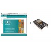
The PsyFi32 development board is mainly based on IC ESP32, so, to start using with the Arduino IDE, you will need to install the ESP32 Arduino Core:
First download the core on GitHub: https://github.com/espressif/arduino-esp32
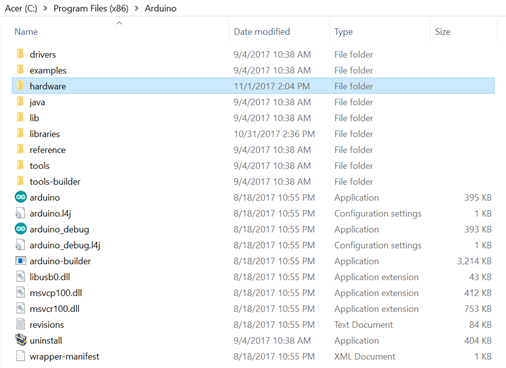
Then go to your Arduino Directory > hardware and create an espressif folder and its sub folder esp32.
Finally extract in this folder the zip file you downloaded previously.
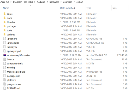
Then you need to install the Xtensa code compiler for the ESP32 :
You only need to navigate to the tools folder and right click on get.exe and run it as administrator.
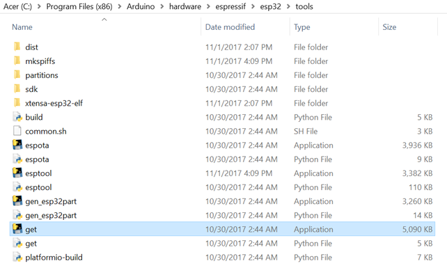
After the installation the xtensa-esp32-elf folder should appear in the tools folder.
The ESP32 Arduino Core is now installed and you can now open your Arduino IDE.
Plug the ESP32 into your computer using a micro USB cable.
Then in your Arduino IDE navigate to Tools > Board > ESP32 Dev Module to select your board.
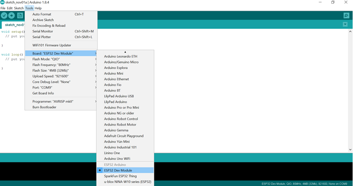
And remember to choice the right Port (mine is COM 9).
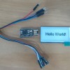
You can now upload a simple example code like the Blinking sketch to see if your board is working well.
You just need to add the following line at the beginning of the sketch to make the on-board LED blink.
On PsyFi32 board, the LED is on pin #5, so let’s define it at the beginning:
int LED_BUILTIN=5;
Then upload the code to PsyFi32,
You will see the red LED is blinking as we expect.
Some properties of the PsyFi32/ESP32:
| Features | Ardunio UNO | PsyFi32/ESP32 |
| Number of Cores | 1 | 2 |
| WiFi | No | Yes |
| Bluetooth | No | Yes |
| Architecture | 8 bit | 32 bit |
| RAM | 2KB | 512KB |
| Flash | 32KB | 16MB |
| CPU Frequency | 16MHz | 160MHz |
| GPIO PINs | 14 | 18/36 |
| BUSSES | SPI, I2C, UART | SPI,I2C,UART,I2S,CAN |
| ADC Pins | 6 | 10/18 |
| DAC Pins | 0 | 2/2 |
PsyFi32 PINMAP :
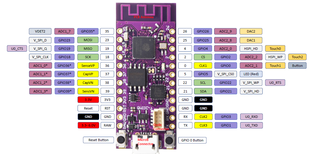
Check out the full PinOut PDF version here:
If you have any problem, thoughts, ideas or wishes, please leave a comment here, or send an email to shop@smart-prototyping.com.