

E-ink Display Module Tutorial Part 2 - Images
Updated August, 2017 to reflect correct connections
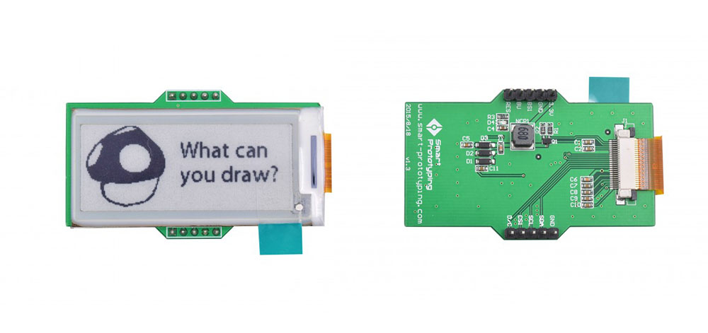
So, you’ve graduated from materializing text onto the E-Ink Display Module and are now ready to stamp an image onto your everlasting display. What worthy design will you work with?
For this step-by-step tutorial, we'll first show you how to upload a pre-installed image onto your module and then guide you through making your own image using a .bmp file.
(Note: The method of connection is different from our E-Ink Display Module Tutorial Part 1, feel free to skip the breadboards and connect the two devices directly as in Part 1)
If you are interested to see how E-Ink works, check out this short video: http://bit.ly/HowE-InkWorks
Things to prepare:
Hardware:
- Arduino UNO board
- E-Ink Display Module
- A-B USB Cable
- Male to male jumper wires
- Two breadboards
Software:
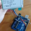
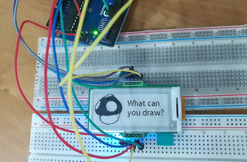
STEP 1. Connection
Below, is the pin layout of the E-Ink module for your reference.
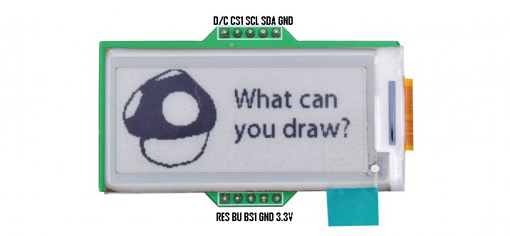
Connect the module to the Arduino Uno as follows:
| E-Ink Module | Arduino Uno |
|---|---|
| D/C | D5 |
| CS1 | D6 |
| SCL | D13 |
| SDA | D11 |
| GND (either is ok, but we like to use the one next to SDA) | GND (either is ok, but we like to use the one next to 5.5V) |
| RES | RESET |
| BU | D7 |
| BS1 | D8 |
| 3.3V | 3.3V (5V is also fine) |
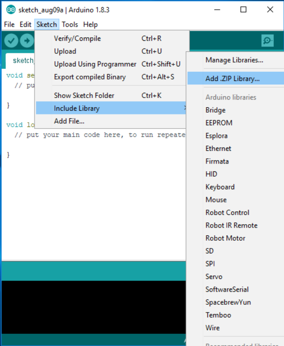
STEP 2: Install the Arduino library
- Download the E-Ink Library as a .zip file
- Open your Arduino IDE and import the E-Ink Library into it (Install the IDE if you haven’t already at www.arduino.cc/en/Main/Software)
- In the Arduino IDE, go to Sketch > Include Library > Add .zip library
- Choose the SmartEink_Arduino_Library.zip file that you just downloaded
- You should see that the library was added successfully
STEP 3: Upload and run the code
- In the Arduino IDE, navigate to File > Examples > SmartEink > ShowBitMapDemo. Load up the example sketch. A new window will open with default code like the code below:
- Before you upload the code to your Arduino Uno, make sure you have the correct board type and port selected under the Tools tab:
1. For the board, select Arduino/Genuino UNO
2. For the port, select the correct COM Port of your device. In our case it is COM7 - Upload the code.
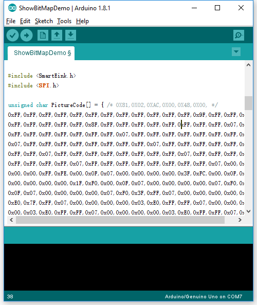
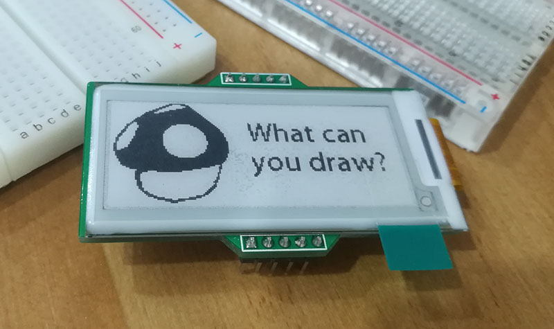
The code should’ve successfully uploaded a picture. You can try unplugging the Arduino Uno from its power source. The module will display this image until you upload new code to the Arduino.
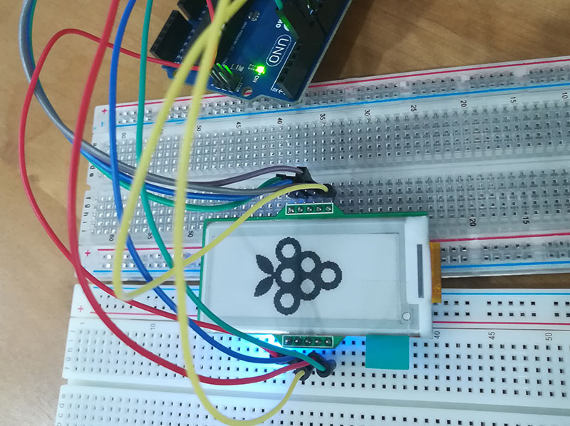
Step 4. Display your own design
- First, pick a picture you’d like to display. I picked cartoon grapes for this tutorial from this link: https://maxcdn.icons8.com/Share/icon/Plants//grapes1600.png
- The file size is 1600x1600 pixel and in a png format that we will need to convert to 172x72 pixel, bmp format. I used photoshop to change the picture size and to save it as bmp.

- Then use the software Image2Lcd to open it, copy the options as they appear in the following screenshot, click save, and you will get the c array code for this picture.
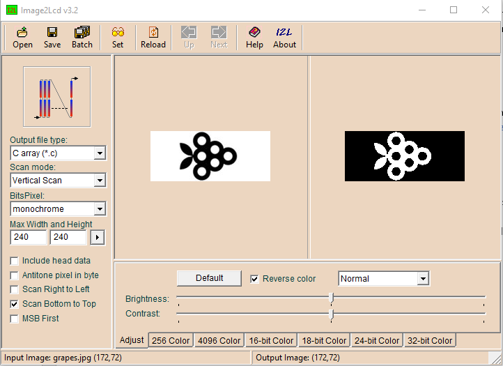
- Copy this array code starting from after the { symbol to right before the last comma at the end of the string of code. In the ShowBitMapDemo page in the Arduino IDE, paste the code right after the { that is following "unsigned char PictureCode[]",
- Upload the code to the Arduino board and wait for the module to display the image you selected.
You can also click here to get the mushroom bmp c array code.zip.
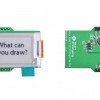
Congratulations! You have your E-Ink display module up and running! Keep going and try uploading different pictures. Go ahead and post your display in the comments below. What can you draw?
3 Comment(s)


Hello David, do you mean you want to display text or numbers? not a picture? Please check this tutorial: https://www.smart-prototyping.com/blog/e-ink-display-module-tutorial-1 use Eink.EinkP8x16Str(x,y,"text") function.

It works though the instructions and picture are not consistent. For example 3.3V is not mentioned. Do both GND have to be connected. Why is 5V connected in the pictuire. And the wires on the picture do not all match the instructions. I've got it working, but I hope this mstep-by-step will be improved.
This is what I connected to get it working. Different from the picture, I did not connect the 5V. In the INO-example-scripts which are given, some connections are mentioned too: Einkmodule - Arduino UNO; D/C - D5; CS1 - D6; SCL - D13 (=SCK); SDA - D11 (=MOSI); GND - GND; RES - RESET; BV - D7; BS1 - D8; 3.3V- 3.3V