
Spooky Halloween DIY with Arduino
Make a Talking Skull with Arduino - A Halloween Decoration Tutorial
Halloween is almost here and if you don’t have any ideas about how to scare your friends or trick or treaters, that won’t be a problem after reading this tutorial!
In this step-by-step tutorial, we’ll show you how to easily make your own Arduino controlled skull with scary sounds and red, glowing eyes. Building and playing with this project will give you practice with skills like programming, electronics, soldering, etc….
Materials you'll need:
- Male to male jumper wires
- Male to female jumper wires
- 1 small breadboard
- Mp3 player module
- 2 LED lights
- 1 Arduino Uno
- 1 Motion sensor module
- Plastic Halloween skull
- 1 micro SD card (max. 16 Gbs) and an adapter for uploading files
Buy the kit here! (Note: does not include Arduino, Skull, or SD card)
This project also requires some tools:
- A soldering iron (to solder the LEDs)
- Scissors (to cut a hole in the back of the skull)
- A drill is preferable but not necessary (to drill holes in the eye sockets)
- Tape (to tape the LEDs to the eyes)
How does it work?
The main components of the radar sensor are a transmitter and a receiver. The transmitter sends off microwaves with a specific frequency. When these waves strike a moving object, their frequency will be altered and reflected. Once these reflected waves are received by the receiver, it will trigger the MP3 player and the LEDs inside the skull. The MP3 player will play a random track on the SD card while the LEDs in the eyes of the skull will light up.
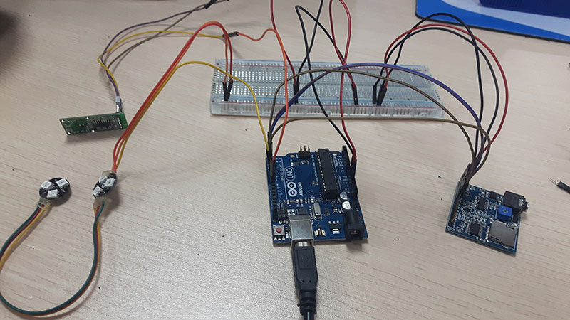
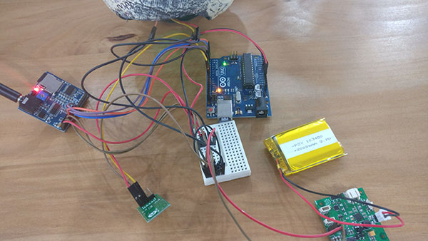
Step 1: Connecting the hardware
- Daisy chain the LEDs together by soldering the wires connected to the Out side with the other LEDs In side. The 2nd LED’s Out side then gets connected to the Arduino and breadboard.
- Connect the power and ground rails on your breadboard to the 5V and GND pins on the Arduino Uno. After doing that, you can connect the power and ground of all your components to the power and the ground rails of your breadboard.
Here are the pin connections to make between the sensors, modules, and the Arduino:
| Motion Sensor | Arduino Uno |
| 3V3 | VCC (5V) |
| GND | GND |
| OUT | D8 |
| NeoPixel | |
| VCC | VCC |
| GND | GND |
| Input (DIn) | D6 |
| Mp3 Module | |
| A1 | D0 |
| A2 | D1 |
| A3 | D2 |
| A4 | D3 |
| GND | GND |
| GND | GND |
| 5V | VCC |
Your electronics are set up! We can move onto the software.
Step 2: Prepare your Arduino
- Connect your Arduino device to the computer using a USB cable
- Open your Arduino IDE (Install the IDE if you haven’t already at www.arduino.cc/en/Main/Software)
- Verify that you have the correct board selected under Tools > Board
- Verify you have the correct COM Port selected under Tools > Port
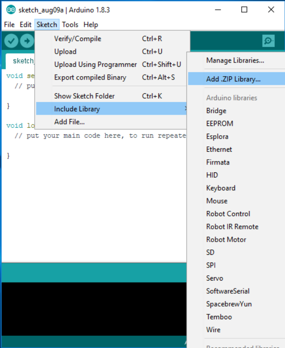
Step 3: Install the Arduino library
- Download the Adafruit NeoPixel Library as a .zip file
- Import the Library
- In the Arduino IDE, go to Sketch > Include Library > Add .zip library
- Choose the file you just downloaded
- You should see that the library was added successfully
Step 4: Upload the Mp3 files and the code
- Find your desired sound-effects online and download the mp3s, we had to cut some of the free tracks we downloaded to get our chilling voices
- Place the soundtracks onto the micro SD card and then place the SD card into the mp3 module
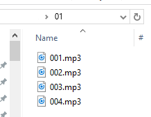
How does the MP3player’s code work?
In our program, A1, A2, A3, and A4 are each linked to one track. When the sensor is activated, the value of these pins is HIGH. Then the random function (audiorandom) will change the value of one of these four pins to LOW and the track linked to this LOW pin will be played. Name the tracks in order of the pins they're connected too i.e. A1 - 001.mp3, etc.
- Next, upload the example code and test out your connections!
Delay() pauses the program for the amount of time (in miliseconds) specified as a parameter. (There are 1000 milliseconds in a second.)
The serial monitor (Tools > Serial Monitor) is a feature of the Arduino IDE that’s very useful to debug your code or when controlling your Arduino from your computer. In our case, you can use it to see if your code is running well.
If your modules and sensors are working, then you can proceed to prepare the skull!
Step 5: Setup the skull and hardware
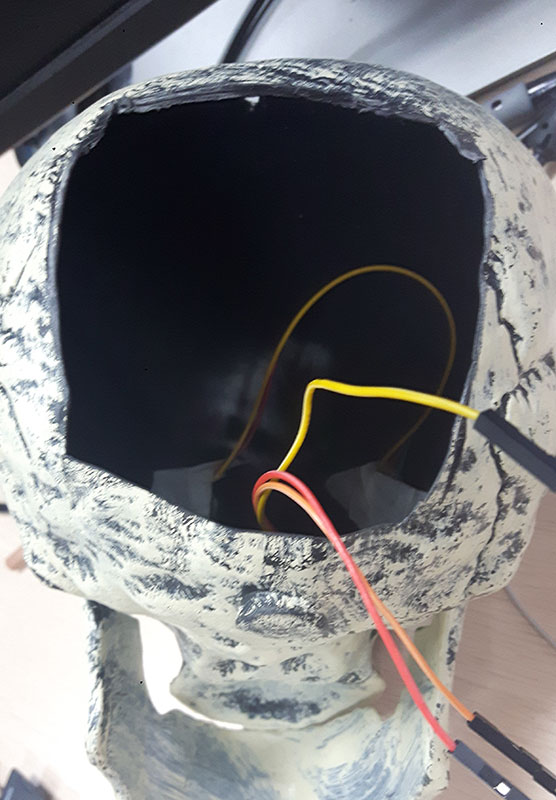
In order to place all the components into the skull, we'll have to first cut off a portion of the back.
- Cut an opening into the skull large enough to fit one of your hands. Hopefully, you have a hollow, plastic one
- Next, drill 3 holes in each socket where the LED lights will be able to shine through. We used a 4 bit which was just wide enough to drill these holes
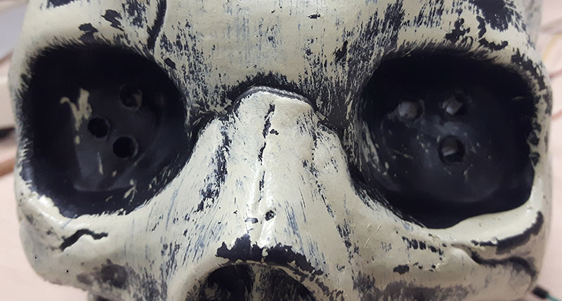
- Then tape the LEDs behind the eye sockets, aligning with the holes you drilled earlier. Make sure to place enough tape so the LEDs won't come off while you're messing with other components and pulling their attached wires
- If you don't have a drill or a skull that would hide the gaping hole in the back of the head, you can use other tools to punch out the holes you need. There are many other ways to handle the skull portion so feel free to unleash your creativity!
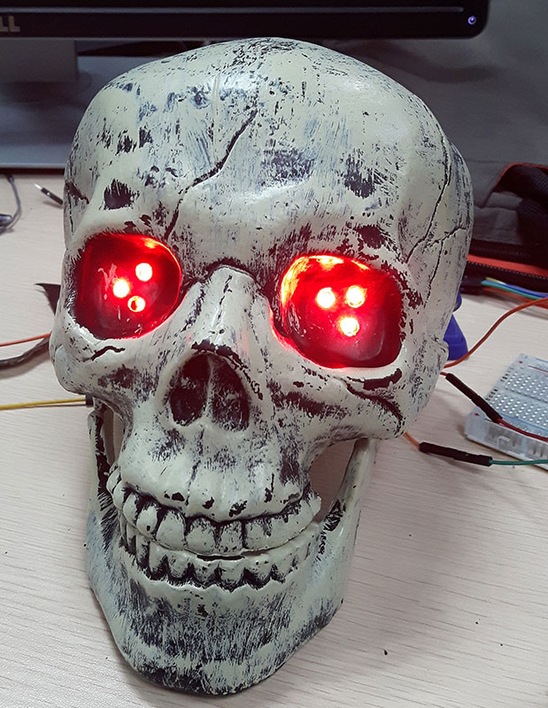
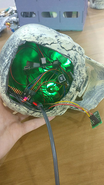
After setting everything up, it should look like this:
If you don't have a drill or a skull that would hide the gaping hole in the back of the head, you can use other tools to punch out the holes you need or hide the components elsewhere. There are many other ways to handle the skull portion so feel free to unleash your creativity!
If you want to fit everything inside the skull, you can use a smaller breadboard. Even the mini breadboard without the power and GND rails will work; just use two rows for GND. You also might have to play around with combinations in the second GND row that will let you power it all up.
And don’t forget the power source! If your project will be working away from a computer or socket, you’ll need a separate power source. It could be as simple as using a power bank or connecting a battery cell to the Arduino. We used a LiPo battery and our powercell.
You can also add cables to give length to the motion sensor so you can mount it in an ideal/hidden place. Since the motion sensor we use has a 360-degree range, we were able to just slip it behind the teeth and still have it pick up motion.
Now that you’ve got your scary skull up and running, you're ready for Halloween! But if you’d like a challenge, you could also improve this project! Add a body, an ensemble, or some motors to make it move. And of course, challenge yourself to set up a spooky set!
Buy your own kit and get started now!