


")

")

Control a Robotic Arm with Zio - Part 1
This blog post is part of the Zio Robotics Series.
You can check other series of the Tutorial below:
- Control Robotic Arm with Zio Part 1
- Control Robotic Arm with Zio Part 2
- Control Robotic Arm with Zio Part 3
- Control Robotic Arm with Zio Part 4
Table of Contents
- Introduction
- Difficulty Level
- Helpful Resources
- Hardware
- Software
- Assembling the Robotic Arm
- Project Schematics
- Zio Modules Connection Setup
- Code
Introduction
In this tutorial, we will build a project where we will use Zio modules to control the Robotic Arm.
This project will teach you how to make your Robotic Arm claw to open and close. This nifty tutorial is suitable for projects where you need your robot to perform a simple pick and place function.
Difficulty Level:
Zio Padawan
Helpful resources:
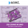
You should have a basic understanding of how to install Zio development boards. In this tutorial, we assume that your development board is already configured and is ready to be set up. If you haven’t configured your board yet check out our Zio Qwiic Start Guide tutorial below to get started:
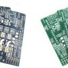
Hardware:
- Zio Zuino M UNO
- Zio 16 Servo Controller
- Zio DC/DC Booster
- 3.7V 2000mAh Battery
- Robotic Arm
Software:
1. Assembling the Robotic Arm
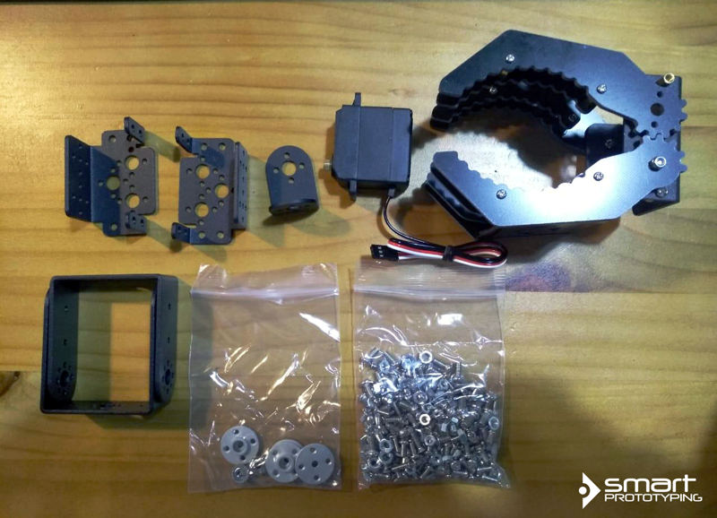
Out of the box, the Robotic Arm comes in parts. Therefore you need to assemble the robotic arm first as this is the most tricky and time consuming part of the process. For most Robotic Arm sets you will get the following parts :
- Claw
- Multipurpose Bracket
- L-Shaped Bracket
- U-Shape Bracket
- Tapping Screws
- Screws
- Servos
- Bearings
Below is a video guide on how to assemble the Robotic Arm that we use for this project.
]
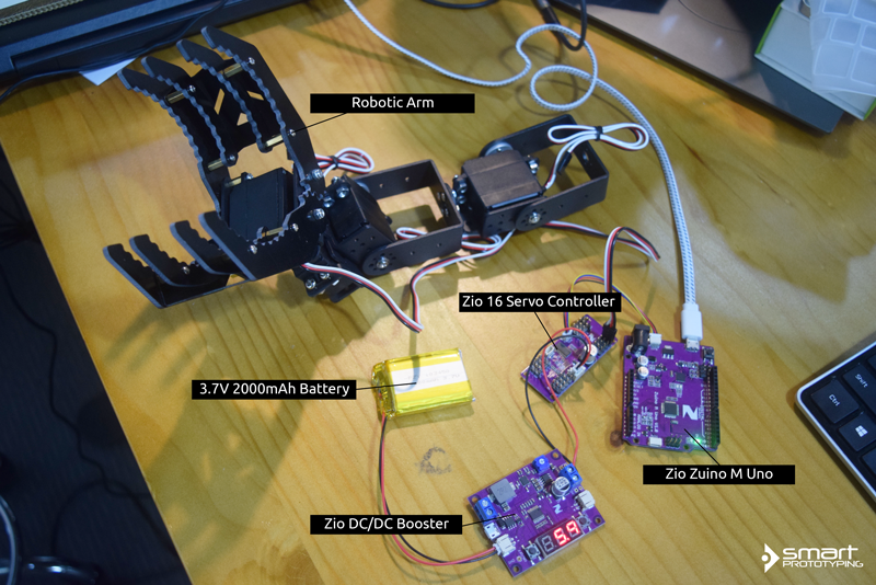
After assembling them, this is what your Robotic Arm will look like.
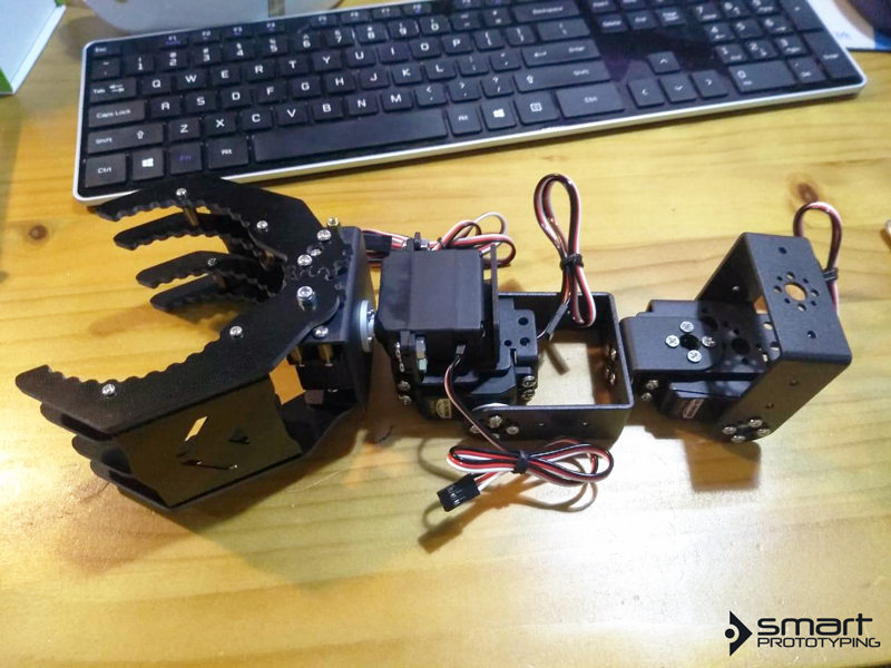
Our Robotic Arm comes with 4 servos. For Part 1 of this project, we will only be utilising one servo that is connected to the claw of the robotic arm.
2. Project Schematics
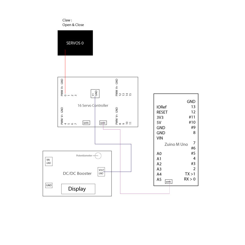
Below is what your final project will look like once you have set up your Robotic Arm with Zio Modules.
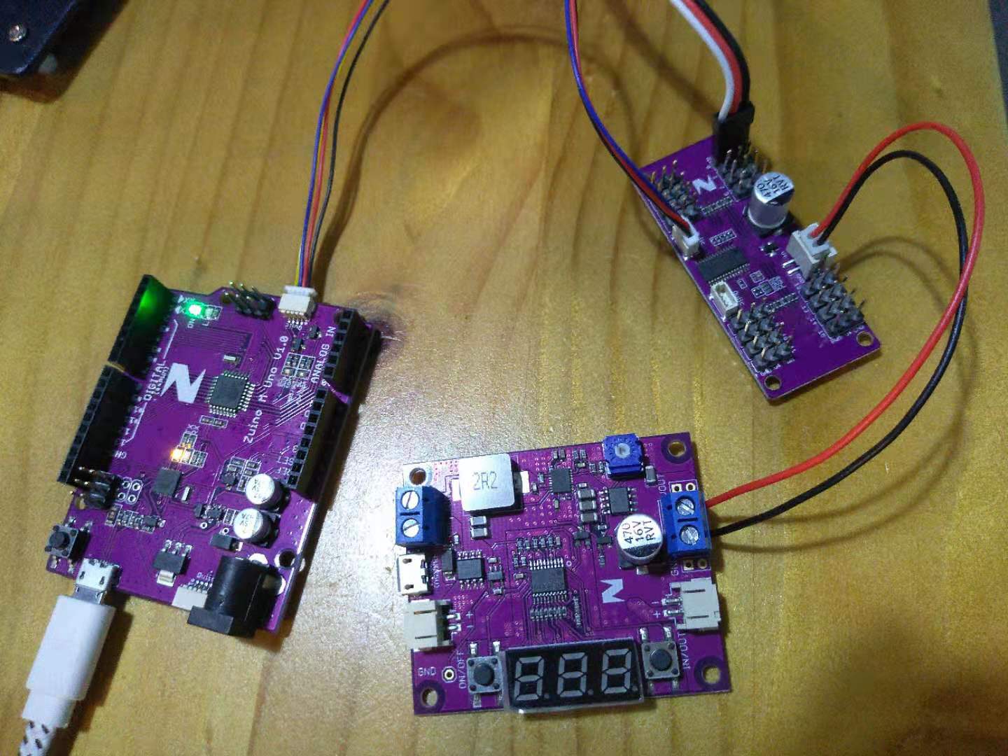
3. Zio Modules Connection Set up
Below is the connection of our Zio modules to be set up with the Robotic Arm. Connecting all the modules together is pretty easy and will not take more than 10 minutes to set up.
Connect the Claw servo to Zio 16 Servo Controller
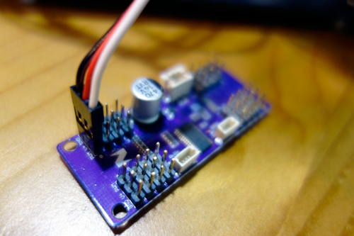
Servo motors have three wires: power, ground, and signal. The power wire is typically red and should be connected to the V+. The ground wire is typically black or brown and should be connected to a ground pin. The signal pin is typically yellow, orange or white and should be connected to a digital pin on the Arduino board.
**Black wire should be with GND, White wire PWM, Red Wire for V+
Connect your 16 Servo to DC/DC Booster and set it at 5.0V.
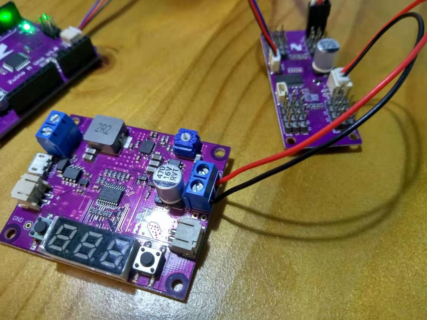
We use a 3.7V battery to power our 16 Servo Controller, which can accommodate up to 5.5V, whereas our Uno is output at 5V is used to control our servo. We use a DC/DC Booster to boost and adjust the battery supply voltage to 5.0.
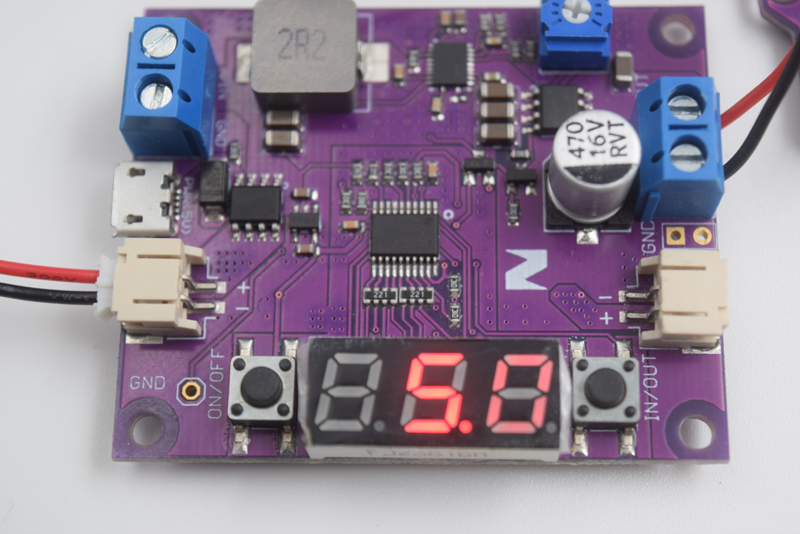
Use the potentiometer on the DC Booster to adjust the voltage until you get 5.0. Push the In/Out button until the display shows 5.0. You need to supply power (3.7V battery) first to your DC/DC Booster in order to adjust the voltage.
Connect Zuino M Uno to the Zio 16 Servo Controller
Qwiic connect Zuino M Uno to the Zio Servo controller with qwiic cable.
4. Coding the Robotic Arm
We use Adafruit PWM Servo Library to code our robotic arm claw function. The following code will command our claw to open and close hence will give our robotic claw the ability to pick up and place objects.
You can find and download the source code for this Robotic Arm Part 1 project on our github page.