

")
")
Introducing I2C with Zio Modules and Qwiic
Robin Sharma said: ‘Small daily improvements over time lead to stunning results’. You might be thinking, ‘Aw, another I2C post?’. Well, there are certainly thousands of information when it comes to I2C. But stay tuned, this is not just another I2C article. Qwiic Connect System and Zio peripheral breakout boards are definitely I²C game changers!
Introduction
If you are building electronic projects and doing awesome things, you might have realized that as your projects get bigger, your breadboard starts looking like a snake pit (a bit messy right?).
In addition, if you have multiple projects going on, you spend a bunch of time switching wires from project to project.
We are makers, so we understand the struggle. Our most recent contribution to the OHS community is a modular prototyping system called ZIO, adopting Qwiic connecting system. Qwiic is a very convenient way to communicate a programmable circuit board to sensors, actuators and breakout boards via I²C.
What is I²C and why we like it
I²C is the most broadly used multi-master bus, meaning that various chips can be connected to the same bus. It is used across many applications between a master and slave or multiple master and slave devices. From microcontrollers, to smartphones, to industrial applications, especially for video devices like computer monitors. It can be easily implemented in many electronic designs (and recently even easier with the Qwiic connector).
If we had to describe I²C in two words, we would probably use simplicity and flexibility.
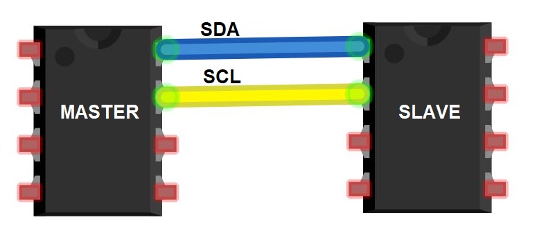
One of the biggest advantages of I²C over other communication protocols is that it is a two wire interface meaning that it needs only two signal wires, SDA (Serial Data Line) and SCL (Serial Clock Line). It might not be the fastest protocol, but it is well known for being very flexible, allowing flexibility in bus voltage.
Another significant characteristic that makes this bus attractive is the fellowship between master and slave. Multiple devices can be connected to the same bus and there’s no need to change the wiring between devices as each device has a unique address (the master selects the device to communicate).
Let’s take a closer look
So, how I²C works?
Earlier we mentioned that one of the most significant features is the voltage allowance, this is possible as I²C uses an open collector (also known as open drain) for both SDA and SCL communication lines.
SCL is the clock signal, synchronizes the data transfer between the devices on the I²C bus and it is generated by the master. While SDA carries the data to send or receive from the sensors or other devices connected to the bus.
The output to the signal is connected to the ground, meaning that each device is imposed as low. To recover the signal to high, both lines are connected to a positive supply voltage through a pull up resistor to be terminated.
With ZIO modules we got you covered, all our breakout boards incorporate the necessary pull up resistor.
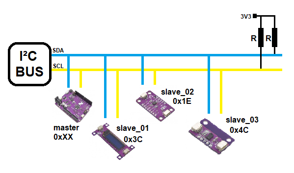
I²C follows a message protocol in order to communicate the master with slave devices. The two lines (SCL and SDA) are common within all I²C slaves, all slaves on the bus listen to the message.
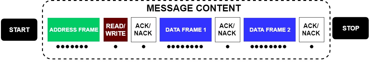
The message protocol follows the format shown in the image below:
It might look complicated at the first glance, but we’ve got a bit of good news. When using Arduino IDE there is the library Wire.h, to simplify all the set up for the I²C message protocol.
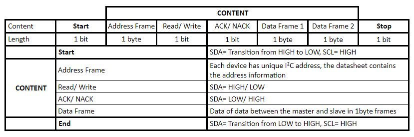
The start condition is generated when the data line (SDA) drops low while the clock line (SCL) still high. When setting up a project on the Arduino interface we don’t really need to worry about generating the start condition, it will be initiated with a specific function (Wire.beginTransmission(slaveAddress)).
In addition, this function also initiates the transmission with the specific slave address. To choose the slave to communicate on the shared bus, the master proceeds to pass down the address to the slave to communicate. After the address is set to communicate to the corresponding slave, de message follows with either a read or write bit, depending on the mode selected.
The salve gives a reply with an acknowledge (ACK or NACK), and other slave devices on the bus discount the rest of the data up till the message is complete and the bus is free. Following the ACK, a sequence of an internal addressing register of the slaves continues the transmission.
When the data is sent, the transfer message ends with a stop condition. To end the transmission the data line changes to high and the clock line remains high.

I²C and ZIO
We figured out that I’d be best to blueprint all information above in a conversation between a master (a.k.a Zuino, our micro) and slaves (a.k.a ZIO breakout boards).
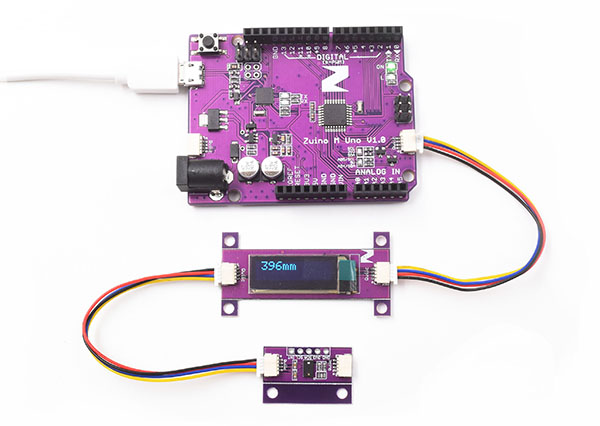
In this basic example we are using the ZIO TOF distance sensor and the ZIO OLED Display. The TOF gives the distance information while the ZIO Oled displays the data. The components and devices used:
- ZUINO M UNO - the Master
- ZIO OLED Display - Slave_01
- ZIO TOF Distance Sensor - Slave_02
- Qwiic Cable - Easy connection for I²C devices
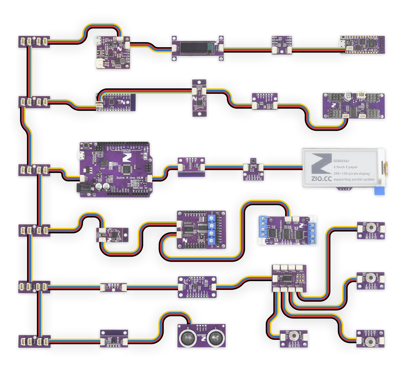
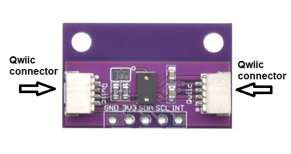
Here's how easy is to connect the boards to each other using Qwiic, no breadboard needed, additional cables nedded or ZUINO pins. The serial Clock and Data line of the ZUINO is automatically connected to the Distance sensor and OLED by using the Qwiic connector. The two other cables are the 3V3 and GND.
First off, let's have a look at the information needed, to communicate the master with the slaves we would need to know the unique addresses.
| Device | Part Number | I2C Address | Datasheet Link |
| ZIO Distance Sensor | RFD77402 | 0x4C | Datasheet |
| ZIO OLED Display | SSD1306 | 0x3C | Datasheet |
To find the unique address for the slave devices open up the datasheet provided. For the Distance sensor the address is provided at the Module Interface seccion. Every sensor or component has a different datasheet with different information provided. Sometimes can be challenging to find it on a 30 page datasheet (hint: open up the find tool on the PDF viewer and type “address” or “device ID” for a quick search).
Now that the unique address for each device is known, to read/ write data, the internal register address has to be identified (also from the datasheet). Having a look at the ZIO Distance sensor datasheet the address to get the distance corresponds to 0x7FF.
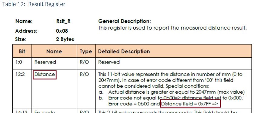
In this particular case we really don’t need this information for using the sensor as the library does it already.
Next step, hands on the code. ZUINO M UNO is compatible with Arduino IDE, which makes the setup a lot easier. The libraries needed for this project are the following:
Wire.h is an arduino library, the two Adafruit libraries are used for the OLED and the last ones is used for the Distance sensor. Check this tutorial on how to link *.zip libraries to Arduino IDE.
Looking at the code, first the libraries have to be declared as well as the address for the OLED.
In the setup() the transmission begins and text is displayed for the distance sensor functionality.
The loop() takes measurements on the distance and the OLED prints it.
Check the example source code on github link.
Using both breakout boards is pretty easy in all senses. On the hardware side the Qwiic connector makes the hardware setup faster and a lot less messy than having a breadboard and jumper wires. And for the firmware, using the corresponding libraries for the I2C comunication, the sensor and the display makes the code a lot more simple.
FAQs
What is the maximum cable length?
The maximum length depends on the pull up resistors used for SDA and SCL and the cable capacitance . The resistors also determine the bus speed, the lower the bus speed, the longer the cable limit. The cable capacitance limits the number of devices on the bus, as well as the cable length. Typical applications limite the wire length to 2.5-3.5m (9-12ft) but there is variation depending on the cable used. For reference, maximum length on I2C applications using shielded 22 AWG twisted pair cables is about 1 m (3 ft) at 100 kbaund,10 m (30ft) at 10kbaud.
There is some sites like mogami or WolframAlpha that allow to estimate the cable length.
How to connect multiple devices on the same bus?
I2C is a serial bus, where all the devices are connected to a shared bus. With Qwiic connector the different breakout boards can be connected one after each other using the Qwiic connector. Each board has at least 2 Qwiic connectors.
We created different boards to solve some of the Qwiic and I2C limitations. Zio Qwiic adapter board is used to connect via Qwiic devices without a Qwiic connector, using Qwiic to breadboard male header cable. This simple trick creates unlimited possibilities.
To connect different devices on a bus or tree network we came up with the Zio Qwiic Hub.
Last but not least, the Zio Qwiic MUX allows the connection of two or more devices using the same address.
What is the I2C termination?
I2C is required to terminate, so the line is free to add other devices. This may be a bit confusing, as the termination term is commonly used to describe the bus pull-up resistors (to provide a default state, in this case to supply current to the circuit). For Zuino boards, the resistor value is 4.7kΩ.
If the termination is omitted, there will be no communication at all on the bus- the master wouldn’t be able to generate the start condition, so the message won’t be transmitted to the slaves.
For further information and Zio capabilities check the latest Zio products. The goal on this article is to explain the I²C communication basics and how it works with Zio and Qwiic connector. Stay tuned for more updates.