


")

")

Zio Current & Voltage Sensor Qwiic Start Guide
This post is part of our Zio Qwiic Start Guide Blog Series.
Table of Contents
- Introduction and Overview
- Setting-Up your Zio Qwiic Current & Voltage Sensor
2.1. Helpful Resources
2.2. Installing Arduino Libraries - Battery Measurement Example
- In-Circuit Measurement Example
Introduction and Overview
A small and versatile board, it can be used for measuring the power consumption of your projects, estimating battery life, measuring battery levels, and power management systems.
The INA219 is capable of measuring voltages of up to +26VDC, and a maximum current of 3.2A, by using a 0.1 ohm shunt resistor (Labelled R100). The current is calculated by dividing the voltage drop across the shunt, by its resistance; with the voltage and current known, the power can be calculated. This is achieved with the necessary Arduino Library, and example code provided here.
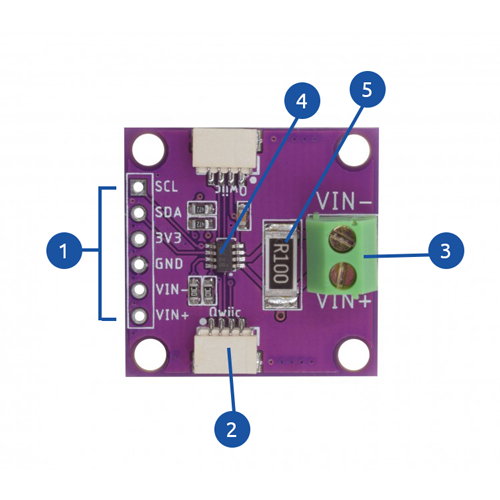
- Power and Logic Pins
- Power Pins: VIN+, VIN-, GND, 3V3
- Logic Pins: SDA, SCL
- Qwiic connector
- Vin+ and Vin- Terminal Block
- INA219 IC
- 100R Shunt Resistor
Setting-Up your Zio Qwiic Current & Voltage Sensor
Helpful Resources:
This qwiic guide has a separate post on our development board guides. Check them out below:
Installing Arduino Libraries
You will need to download and install this library to your Arduino IDE before you can start programming your Zuino board for the Zio Qwiic Current & Voltage Sensor.
Click the link above to download the .Zip file. Then, go to your Arduino IDE and select the "Sketch" tab, then "Include Library" --> "Add .Zip Library", and select the file you just downloaded.
Upload the Code
After installing the Arduino library, you can connect the Zuino to the PC via the USB cable.
Once connected to your PC, you can navigate to the new library example code.
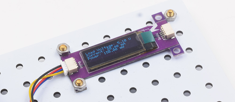
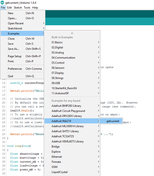
Go to File --> Examples --> Adafruit INA219 --> GetCurrent; as shown above. If everything is connected properly, you should then be able to click upload, and have the data displayed to the OLED display*.
*If you do not have an OLED display, you can simply omit it from the circuit, then open the Serial Monitor (Tools --> Serial Monitor (Use 115200 Baud Rate)), and view the data there.
Battery Measurement Example
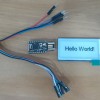
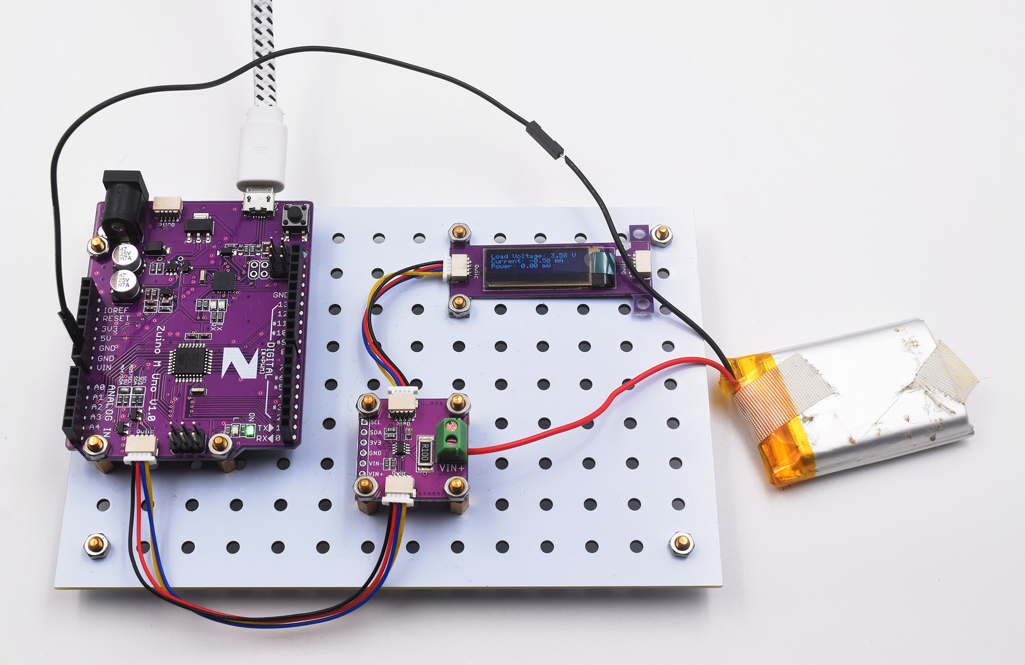
For this example, we will monitor the voltage and current of a coin cell battery, using the Zuino M Uno microcontroller development board, and display the results on an OLED screen (ZIO OLED Display).
The image below shows the connections made between each of the three components using the Qwiic Connectors.
Each component is connected via two Quiic connectors, one from the Zuino to the INA219 Board, and another to the OLED display from the INA219 Board.
One loose wire is connected from the VIN+ connection of the green terminal block, and another to Ground; this can either be on the Zuino, or INA219 Board as they are both connected. It is recommended to have both connections made directly to the terminal block of the measurement board, with the shortest possible connections, for better accuracy.
In-Circuit Measurement Example
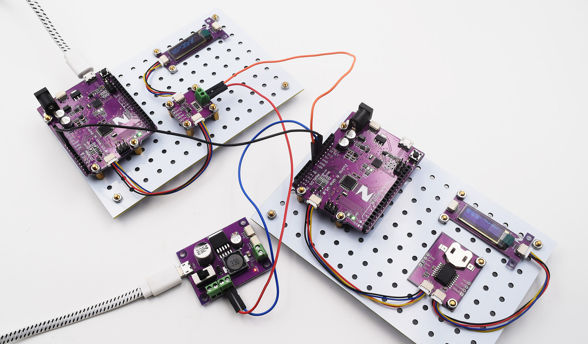
In this example, we will use our measurement circuit to find the current draw of a different circuit/project. Simply changing a few connections will enable us to measure the current, voltage and power draw of a Device Under Test (DUT).
This time we are using a separate power module as well to provide enough power for the DUT, and the rest of the circuitry.
Shown below are the new connections between the INA219 module, Zuino, and the DUT.
The connections are the same as in the previous example, however, we are now powering the DUT (The circuit on the right of the image) through the INA219 Terminal Block.
+5V from the Power Module (LM2596 Power Adapter) is connected to the VIN+ pin of the INA219 Board, and the VIN- pin from the INA219 Board is then fed to the VIN pin of the Zuino. Then, connect both Zuino Ground pins; one back to the Power Module, and the other to the Ground of the Measurement Circuit.
Both the Power Module, and the Measurement Circuit are separately powered from two micro USB cables; the Power Module powers the DUT.
After making all of the necessary connections, you can use the same code as in the previous example, upload it and test the circuit! You can still use the Serial Monitor
(Use 115200 Baud Rate), if you're not using a display.