

")
")

")

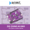
Zio 4 DC Motor Controller Qwiic Start Guide
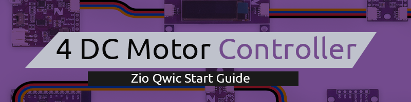
This post is part of our Zio Qwiic Start Guide Blog Series.
Introduction
Drive two motors at up to 1.2A of constant current with the Zio Bidirectional 4-Channel DC Motor Controller. Dual H-bridges will allow you to also brake and stop in addition to controlling the direction and speed of the motors. Two input signals (IN1 and IN2) can be used to control the motors with the following functions: CW, CCW, short-brake, and stop.
You can independently control the two bidirectional DC motors at once. The PWM input allows you to spin the wheels in either direction and at whatever speed you like.
This board also comes equipped with Qwiic connectors so you can quickly and easily daisy-chain to other modules in the Qwiic ecosystem.
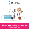
We use motor controller to control motors like a water pump that we use to build an automated watering plant system.
Zio Qwiic 4 DC Motor Controller Overview
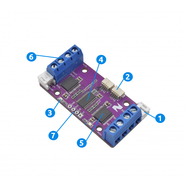
1. Battery Supply Connector
2. Qwiic Connector System
3. LED
4. PCA9685 I2C IC:
- Selectable Address: 0x40 - 0x7F (default 0x40)
5. TB6612FNG Driver IC for Dual DC Motor
6. Dual H Bridges
7. ISP Power & Logic Pins:
- Supply Pins: GND, 3V3
- I/O Pins: 15,14
Configuring your Zio Qwiic 4 DC Motor Controller
Difficulty Level:
Helpful resources:
You should have a basic understanding of how to install Zio development boards. In this tutorial, we assume that your development board is already configured and is ready to be set up with our Motor Controller. If you haven’t configured your board yet check out our development boards Qwiic Start Guide tutorial below to get started:
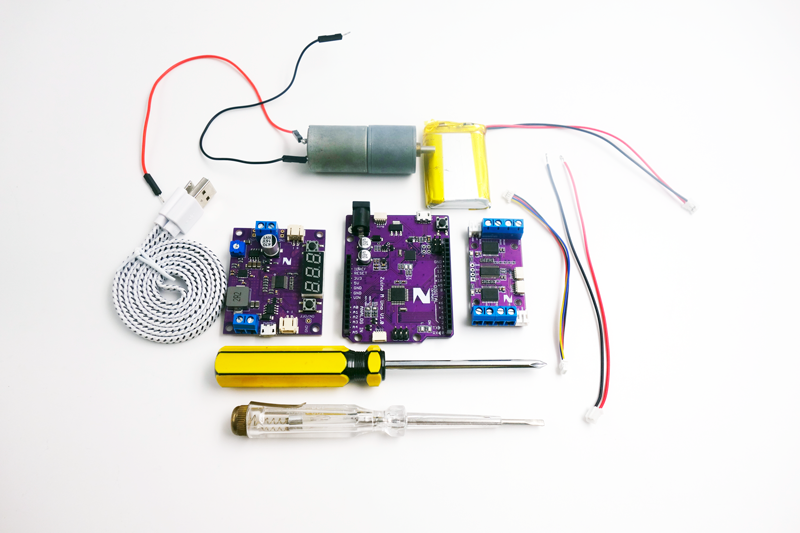
Setting Up
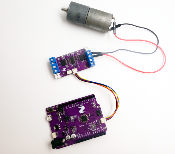
Modules Connection Set up
Below is what the final set up will look like after you connect all the modules and components together.
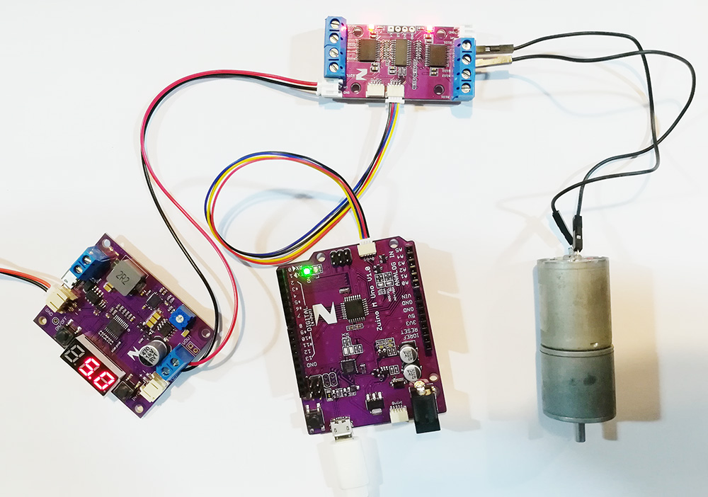
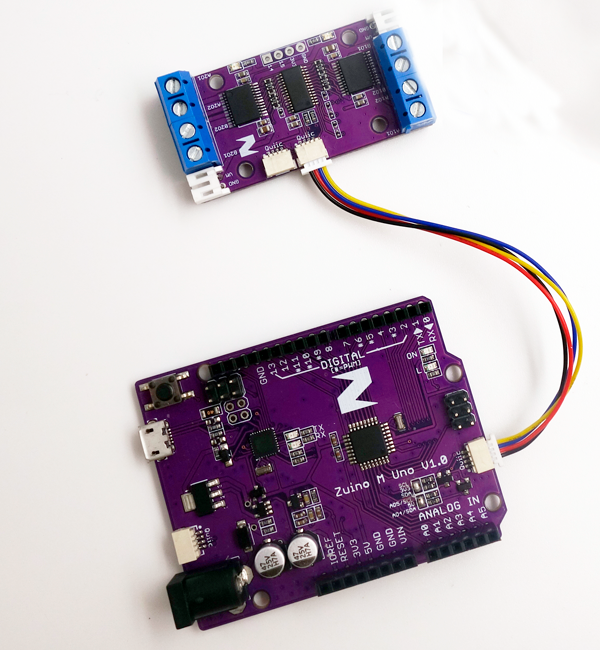
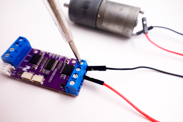
Step 1 Connect Zuino M Uno to the 4 DC Motor Controller
Setting up your 4 DC Motor Controller to your Development board is super easy. Just daisy chain the modules together with a qwiic cable and you’re all set up!
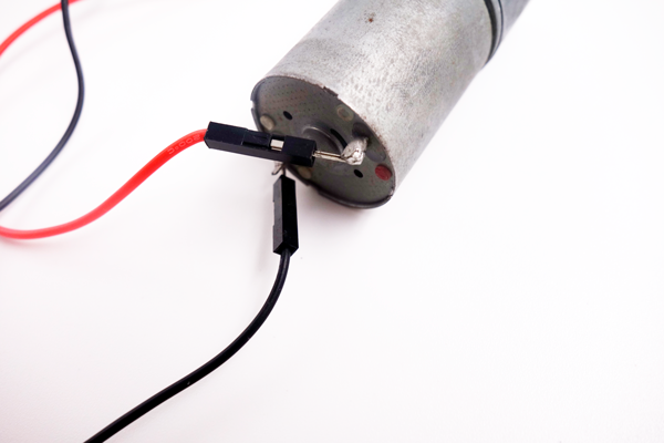
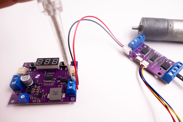
Step 2 Connect 4 DC Motor Controller to a Stepper Motor
Firstly, solder the Jumper wires together to the Stepper Motor. Then connect the wires from the Stepper motor to the 4 DC Motor Controller as shown below:
Step 3 Connect Zio DC/DC Booster to your 4 DC Motor Controller
You need to adjust the voltage of your DC/DC Booster for the 3.7V Li-on Battery to provide sufficient power to your DC Motor at 5.0V.
Adjust the potentiometer of the DC Booster to change the voltage to 5.0 as shown below.
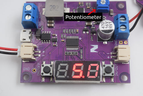
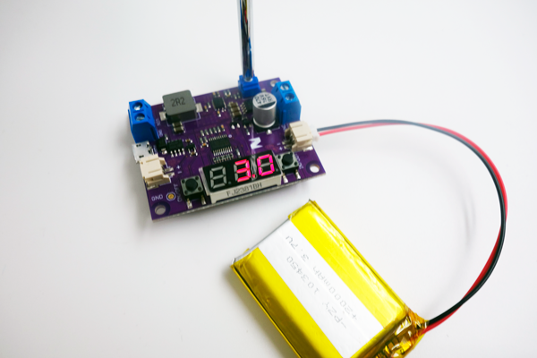
Using a Flathead screwdriver, wire the 4DC Motor Controller to your DC/DC Booster.
Install library
You need to install the following libraries to your Arduino IDE before you can start programming your Zuino board with Zio 4 DC Motor Controller.
Download the following libraries and save it on your local Arduino IDE libraries folder:
Adafruit PWM Servo Driver library
To install the libraries open your Arduino IDE, go to Sketch tab, select Include Library -> Add .Zip Library. Select the above libraries to be included on your IDE.
Arduino has a handy guide on how to install libraries to your Arduino IDE. Check them out here!
Upload and Run Demo code
Download the demo code below and run your code to your board.
You can find and download the source code for this tutorial qwiic start project on our Github page.
If you have configured it correctly your stepper motor will now vibrate once you run your code.
That's it! You can also check out other tutorials and projects on Zio 4 DC Motor Controller here to get you inspired~