


Zio Zuino M Uno Qwiic Start Guide
This post is part of our Zio Qwiic Start Guide blog Series
Table of Contents
Introduction
An Arduino/Arduino Uno - R3 compatible microcontroller based on ATMega238 fitted with Qwiic connector for qwiicker prototyping of your Arduino projects. This beginner-friendly board is open source, and comparatively inexpensive to have in your future tinkering projects.
Zuino M Uno comes with all of the functions and features that you know and loves from the Arduino Uno, with the added bonus of Qwiic connecting system, of course! The familiar header pins will allow you to use it with any Arduino shield or other modules that lack a Qwiic connector.
In this Qwiic Start guide, you will learn what’s awesome about our Zuino M UNO board (Yes, it’s awesome!), the components needed to Qwiic Start your projects, and how easy it is to configure Zuino with both Qwiic and non-Qwiic compatible modules! You will try out two Arduino basic example codes to get you started.
Zuino M UNO Qwiic Board Specs:
Microcontroller: Atmega328P
Operating Voltage: 5V
Input Voltage: 7-12V
Digital I/O Pins: 14 (6 provide PWM output)
PWM Digital I/O Pins: 6
Analog Input Pins: 6
DC Current per I/O Pin: 20 mA
DC Current for 3.3V Pin and Qwiic: 50 mA
Flash Memory: 32KB (0.5 KB is used by bootloader)
SRAM: 2 KB
EEPROM: 1 KB
Clock Speed: 16 MHz
Dimensions:
Weight: 18.7g (0.66oz)
Zuino M UNO Qwiic Board Overview
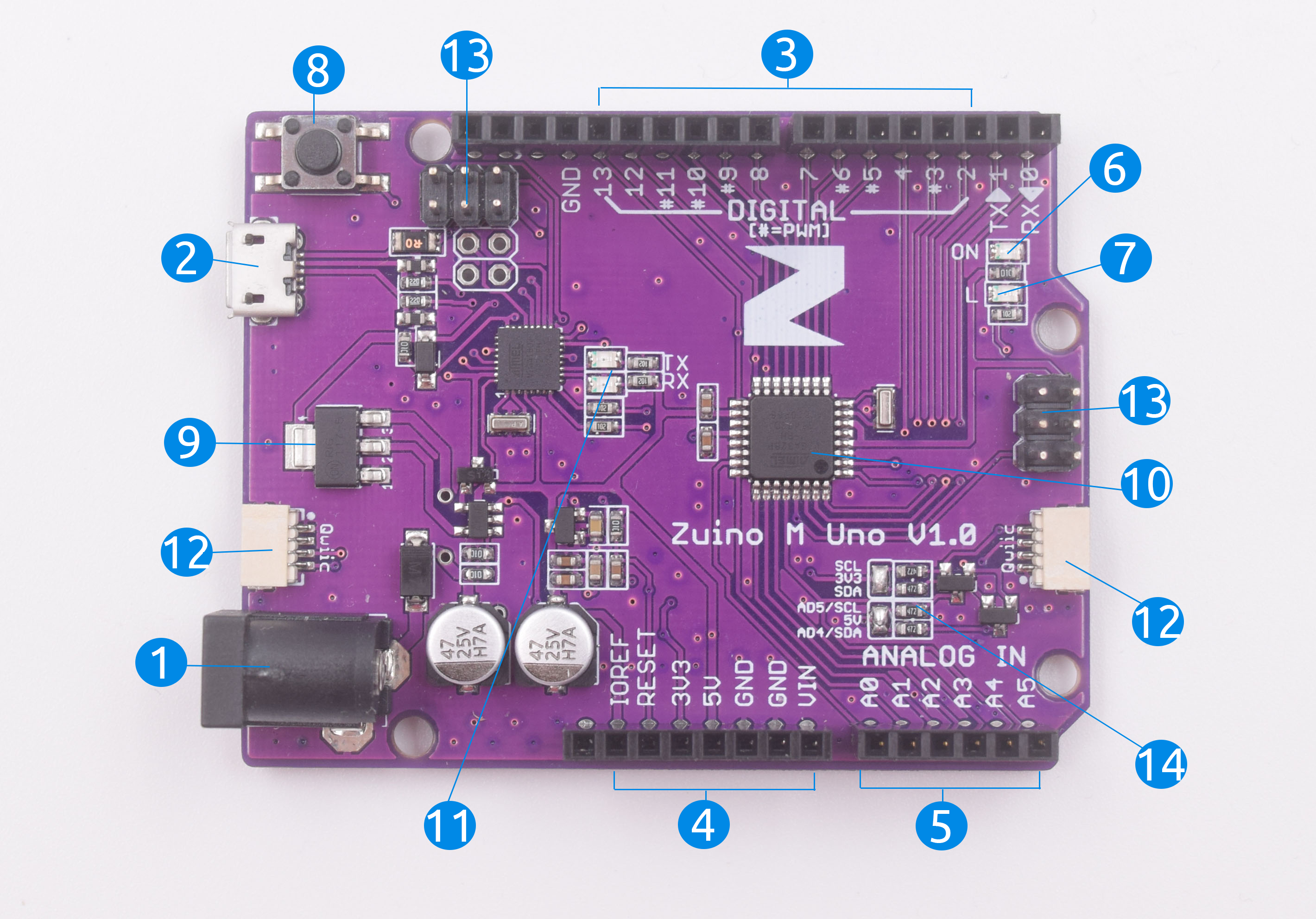
Barrel Jack
Just like any Arduino or Arduino compatible board, it needs a power source and our Zuino board can be powered via either the USB or barrel jack connectors. Regulated power supply recommended for our Zuino is 7-12V.
Note: you cannot power the Zuino M Uno via Qwiic, as it is a 5V device, and does not include a 3.3v-to-5v boost converter.
USB
As mentioned earlier, USB is another way that you can supply power to our Zuino board. You can hook it up using either a Micro B to A USB cable (if connecting via computer) or a USB wall charger (regulated at 5V).
Hooking up Zuino via USB connection to your computer is also how you will upload code onto your board. Our board can be easily programmed using the Arduino IDE, the primary reason this microcontroller is the nearly ubiquitous introduction to embedded computing for the last decade.
You need to install the Arduino IDE in your computer before you can code and upload your code to Zuino microcontroller. We will explain this more on the following section on Configuring your Zuino Board.
Digital Pins
These black plastic we called ‘headers’ are the digital input and output (I/O) pins used to connect to, for example, sensors, LEDs, etc to interface the Arduino to connect with other modules or hardware.
Our awesome board has digital pins labeled from 2 - 13. Pins marked with ‘#’ (3,5,6,9,10,11) are normal digital pins that can also serve as Pulse-Width Modulation (PWM) pins. PWM are analog outputs which can be used to, for example, dim LEDs.
Power Pins
Also referred to as ‘power header’ is mostly full of voltage supply pins used traditionally to supply voltage for other pieces of hardware (like LEDs, potentiometers, and other circuits).
3.3V and 5V: These pins are regulated at 3.3V and 5V voltage sources respectively.
GND(3): The ‘GND’ pins are the common ground - used to ground your circuit. Our board has 3 GND pins.
VIN: The input voltage and will be equal to the voltage of your input supply if you have a wall adapter connected. If you’re powering the board via USB, VIN should be around 5V.
Analog Pins
Our Analog In pins also referred to as the ‘analog header’, is an analog-to-digital converter use for to read the analog signal ranging from 0-5V from an analog sensor and convert it into a readable digital value.
Our Zuino board has six pins labeled A0 - A5, all of which can also serve as digital inputs and outputs.
Power LED Indicator
If you look closely on our board, next to digital headers there is a label marked ‘ON’. This, my friend, is the power LED indicator. If you want to know if your board is powered up nicely, you should be able to see this LED lights up brightly. If this light doesn’t turn on, there’s a good chance something is wrong.
Pin 13 LED
This is a “feature” originally introduced in revision 3 of the Arduino Uno board. Our Zuino board, however, has the same LED plus resistor combination driven by pin 13. Thus, the name Pin 13 LED. Pretty useful to test with ‘Blink” example code provided in the Arduino IDE.
You will see this exactly next to the Power LED Indicator marked with ‘L’. This is programmed to turn on by default once you power your board- pinMode(LED_BUILTIN, OUTPUT).
Reset Button
As the name applies, this is the button you will use to reset the code that you have loaded onto the board. Pushing the reset button will reset the code on your board, assuming it is not on repeat.
Voltage Regulator
It does exactly what it says – it controls the amount of voltage that is let into the Zuino board. You should not mess with this feature but it is good to know what it does for reference purposes. Basically, it will turn away an extra voltage that might harm the circuit. Of course, it has its limits, so don’t hook up your board to anything greater than 20 volts.
Main IC
This is the brain of our Zuino board, the microcontroller main Integrated Circuit (IC). Our board IC is Based on the ATmega328 by ATMEL. In a nutshell, our IC runs on
Flash Memory: 32KB (0.5 KB is used by bootloader)
SRAM: 2 KB
EEPROM: 1 KB
Clock Speed: 16 MHz
TX RX LEDs / Serial LEDs
TX RX is short for transmit and receive respectively. The pins are responsible for serial communication.
Qwiic Connector
Our Zuino board is incorporated with the Qwiic Connector System. Qwiic is an ecosystem of I2C sensors, actuators, shields, and cables that make prototyping faster and less prone to error.
We have a separate page dedicated to explaining what Qwiic connector is. You can learn more about it here.
ICSP Headers
Just like the Arduino UNO board, our Zuino also included ICSP pins or ICSP headers. ICSP stands for In-Circuit Serial Programming, consists of 6 pins arranged in 2x3. This is one way how we are able to program codes with Arduino IDE.
Our board has two ICSP headers use with the ATmega328P, and the other for use with the ATmega16U2 chip that implements USB. When present, this allows reprogramming the USB chip.
In a nutshell, the main uses of these ICSP pins are for bootloading and SPI communication.
14. I2C Level Shifter
In simple terms, due to the fact that our Zuino M UNO is regulated at 5V and our qwiic connector is at 3.3V, we need something that can shifts our 3.3V to 5V. You don’t need to install any external level shifters as our Zuino is already pre-installed with one. :)
Configuring your Zuino Board
For this section, you should already have the following:
So you got yourself a new out of the box Zuino board for you to prototype your amazing projects. Awesome! We will show you how easy it is to configure Zuino and ‘Qwiic Start’ your awesome projects!
Installing Arduino IDE
There are two ways you can code using Arduino. The fastest way is to code it online using Arduino Web Editor. The advantages of using Arduino’s online web editor :
No installation needed
Cross-platform as it is browser based
You will always have the most up-to-date version of the Arduino IDE with compatible libraries
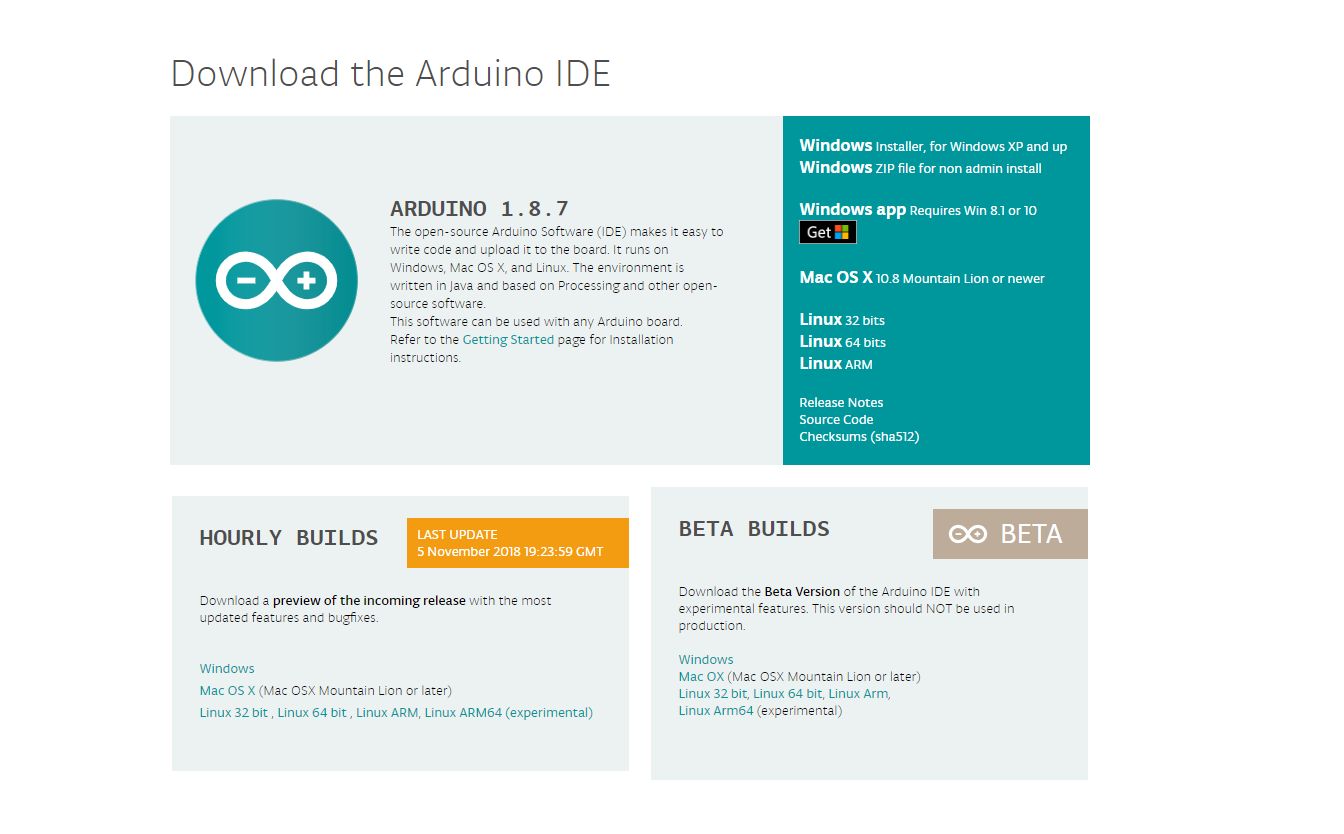
Another way is downloading it to your computer. This is especially handy when you have little to no internet coverage. Pretty useful when you like to code offline.
Download and install Arduino IDE. You should download the latest version according to your operating system. For Windows, if you do not have admin access to install programs, they have a zip file available for this purpose.
Coding your Zuino
Once you have installed Arduino, you can start to program some code and upload it to your Zuino board. It is very easy to configure your board with Arduino IDE. Follow the following steps to get started:
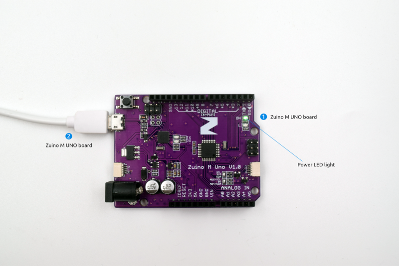
Step 1 Connect your Zuino board to the computer via USB
Your Zuino should emit a light indicating it is powered up.
Step 2 Open Arduino IDE
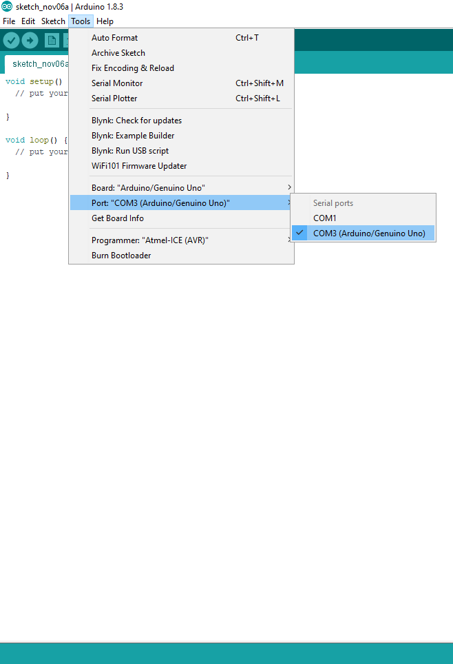
Step 3 Under Tools tab, select board as Arduino/Genuino Uno
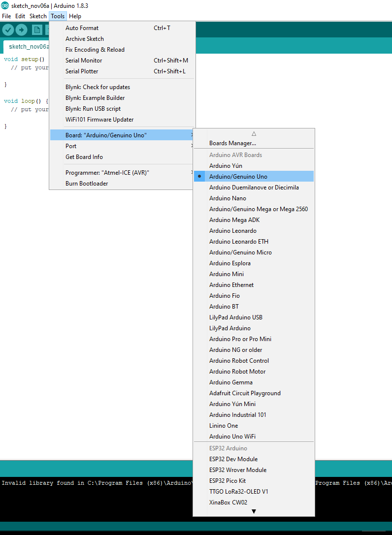
Step 4 Under Port select the COM port that is connected to your Zuino board. In our case, we’re connected to COM 3.
And that’s it! Your Zuino is now configured! Easy peesy! Do check out the example codes for this guide here .