
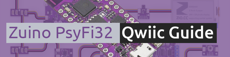
Zio Zuino XS PsyFi32 Qwiic Start Guide
This post is part of our Zio Qwiic Start Guide Blog Series.
Table of Contents
- Introduction
- Zuino PsyFi32 Qwiic Board Specs
- Board Overview
- Configuring your PsyFi32 Board
- Helpful Resources
- Hardware
- Software
- Installing Arduino IDE
- Coding your Zuino PsyFi32
Introduction
This new Open Source ESP32 development board is something that we’re really proud of. The PsyFi32 squeezes an ESP32 development platform into a board with the pinout of Sparkfun’s Pro Micro, and with a footprint that is only a teensy bit longer, is light as a feather and that we hope will be as commonly found on any workbench as oranges are in any grove.
Actually, one might say it looks suspiciously like an ESP32 Thing with slightly fewer pins (don’t worry, we picked them carefully) and without a battery charger. That’s because one of our employees came to us and said: “I want an ESP32 Thing with a Pro Micro’s footprint, and with a Qwiic connector on it.” So here it is.
For your battery charging, monitoring, and regulating needs, we’ve created the ZIO LiPo Battery Manager, which can power the PsyFi32 and plenty of additional sensor and actuator modules over the Qwiic bus.
While you can certainly program this board with the Espressif native toolchain, we’ve made this board specifically for you Arduino fans out there, which is why we picked the form-factor of one of the most beloved and widely-used Arduino-compatible boards.
And while you might not know it from the Sparkfun ESP32 Thing product page, the ESP32 Arduino Core is pretty full-featured at this point, including support for BLE and acting as a web server. (Let us know when you’ve updated your page, guys, so we can update ours. ;) )
In case you’re wondering about the name: it’s a trifecta of fun references.
Zuino PsyFi32 Qwiic Board Specs:
ESP32-D0WDQ6
Weight 2.4g (0.084oz)
Zuino PsyFi32 Qwiic Board Overview

USB
USB is how you can supply power to our Zuino PsyFi32 board. You can hook it up using either a Micro B to A USB cable (if connecting via computer) or a USB wall charger (regulated at 5V).
Hooking up Zuino via USB connection to your computer is also how you will upload code onto your board. Zuino board can be easily programmed using the Arduino IDE, the primary reason this microcontroller is the nearly ubiquitous introduction to embedded computing for the last decade.
You need to install the Arduino IDE in your computer before you can code and upload your code to Zuino microcontroller. We will explain this more on the following section on Configuring your Zuino Board.
GP I/O Button
This GP I/O button is a button function that you can manipulate to work with your module. For example to switch on an LED or even to turn on a Motor by simply coding a few lines of code that is linked to the pin 0 (check the PsyFi32 pinout guide). This means that you do not need an external button with our Zuino XS PsyFi32 :).
Reset Button
As the name applies, this is the button you will use to reset the code that you have loaded onto the board. Pushing the reset button will reset the code on your board, assuming it is not on repeat (loop).
Qwiic Connector
Like all our other qwiic enabled boards, our Zuino PsyFi32 board is also incorporated with the Qwiic Connector System . Qwiic is an ecosystem of I2C sensors, actuators, shields, and cables that make prototyping faster and less prone to error.
We have a separate page dedicated to explaining what Qwiic connector is. You can learn more about it here .
ICSP pins
Although our Zuino PsyFi32 is a Qwiic development board, we also create the board to be compatible and available to non-Qwiic modules. Hence, we installed ICSP pins headers (stackable headers included) that you can solder in to connect with jumper wires.
GPIO pins: 18/36
ADC pins: 10/18
DAC pins: 2/2
Check out this handy guide that lists out the PsyFi32 pinout.
Main IC
This is the brain of our Zuino board, the microcontroller main Integrated Circuit (IC). Our board IC is based on the ESP32-D0WDQ6. In a nutshell, our IC runs on
Flash Memory: 16MB
SRAM: 512 KB
Clock Speed: 160 MHz
WiFi, BLE
Antenna
As the name applies, this is the button you will use to reset the code that you have loaded onto the board. Pushing the reset button will reset the code on your board, assuming it is not on repeat.
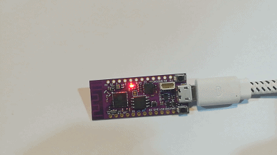
Power LED
This red LED will light up if your Zuino PsyFi32 is connected to a power source. If it doesn’t light up then it means your PsyFi32 board is not working as it should be.
Configuring your Psyfi32 Board
So you got yourself a new out of the box Zuino PsyFi32 board for you to prototype your amazing projects. Awesome! We will show you how easy it is to configure Zuino and ‘Qwiic Start’ your awesome projects!
Helpful Resources:
For our Zuino PsyFi32 board, you need to install a UART driver and the ESP32 Arduino core. Read the following blog post before you start configuring your PsyFi32 to code some programs:
How to start with PsyFi32 (Windows Tutorial)
Hardware:
Zio Zuino PsyFi32
Micro USB Cable
Software:
Installing Arduino IDE
If you haven’t done that already, you need to install the Arduino IDE to configure your PsyFi32.
Download and install Arduino IDE. You should download the latest version according to your operating system.
Coding your Zuino PsyFi32
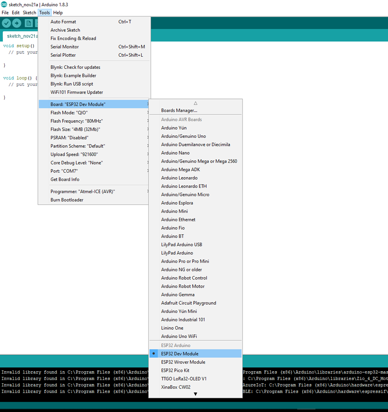
Once you have installed Arduino and the ESP32 core, you can start to program some code and upload it to your Zuino PsyFi32 board. It is very easy to configure your board with Arduino IDE. Follow the following steps to get started:
Step 1 Connect your Zuino board to the computer via USB
Step 2 Open Arduino IDE
Step 3 Under Tools tab, Select board as ESP32 Dev Board
Step 4 Under Port select the COM port that is connected to your Zuino board. In our case, we’re connected to COM 7.
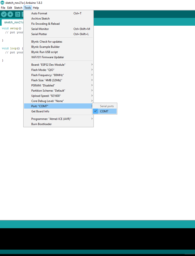
And that’s it! Your PsyFi32 is now configured! Easy peesy!
Test Example Code: Blink
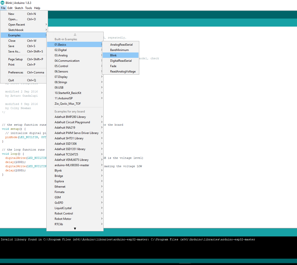
Step 1 Select Example code Blink
From your Arduino IDE, go to the ‘File’ tab, select ‘Examples -> 01.Basics -> Blink
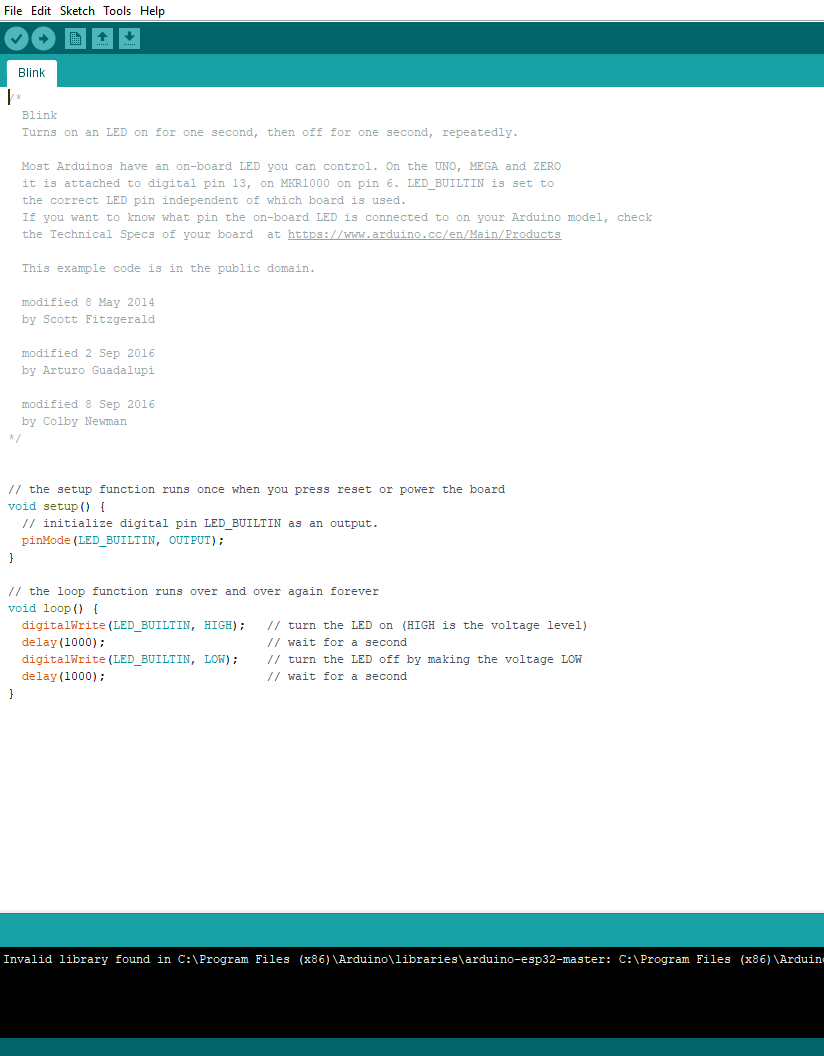
You will be shown with the following code as shown below. Just leave it as is for now.
Step 2 Upload the example code to your board
Click the arrow ![]() button to upload your code to your board.
button to upload your code to your board.
Step 3 Your Zuino board is now blinking!
Step 4 Test by making few changes to the code
Under the setup function you will see the following code:
As explained in the comment section (marked with a forward slash ‘//’), this code pointed to the 13 digital pin, which by default is the pin connected to the LED as explained previously under the board overview. Just leave this code as it is for now as well.
To make changes to the code scroll down to the section under the loop section.
void loop() {
digitalWrite(LED_BUILTIN, HIGH); // turn the LED on (HIGH is the voltage level)
delay(1000); // wait for a second
digitalWrite(LED_BUILTIN, LOW); // turn the LED off by making the voltage LOW
delay(1000); // wait for a second
}
The code under loop function will repeatedly run your code unless you specifically told it to stop. To test your code for BLINK you can make changes to how FAST or how SLOW your LED Blink.
What does the code mean:
HIGH - simply means switching your LED on
LOW - simply means the opposite of HIGH, that is switching your LED off
delay - As the name suggests, this is the time taken for your code to ‘pause’. It is stated in milliseconds (ms) format. For example 1000 = 1 second.
To change how fast or slow your code blinks, you only need to change the time in delay section. Play around with the delay time and see how your Zuino board blinks :).
Aaaaaaaanddd it’s a wrap!
You now have a basic understanding of what your Zuino M UNO can do on its own. Play around with other Arduino IDE Example codes as well to further your understanding on our Zuino board.
Also, if you’re all set to create amazing projects with our Zuino board and create projects with other Zio modules, go and check our other qwiic guide posts to help you qwiic start your journey to tinkering awesomeness!
If you just started out with Arduino IDE, you can try out some basic code examples from the Arduino IDE to get yourself familiar to the code.
In the meantime check out our other awesome and cool Zio projects to give you that qwiic inspiration!