


")
Build an Arkanoid game with Flexible LED Matrix Tutorial
Our very own resident maker, Noah Zerkin, shows you how to build the classic retro games - Arkanoid and Breakout - with the Flexible LED Matrix in this tutorial. We have a video down below for full instructions. But before we jump straight into the project, a couple important notes on best practices not covered in the video:
1) Each WS2812 pixel can easily draw 20mA, and 60mA if all channels are turned up to maximum brightness. For a 768 px panel array, that’s up to 46 Amps! If you want to use an array like this to its full potential, with the option to crank every pixel up to full white at the same time, you’ll want a separate 5v 15A (75W) power supply for each panel. For more conservative use, you can use a 5A power supply for each panel or one 15A supply and appropriately rated wire for the whole installation ought to be fine without much worry about blowing a fuse or setting anything on fire.
2) For this project I’m running off of a computer’s USB port. This would normally be a very bad idea for this many LEDs, but I’ve been careful with my programming and am never lighting up many of them at any given time. You definitely shouldn’t run anything like the Adafruit “strandtest” example on it. Instead, modify an example to light only the last pixels or animate a small pixel cluster down the chain.
3) Other best practices not observed in this video: install a 1000µF cap, rated at 6.3v or higher, across your power terminals before connecting to a power supply. Install a 300-500ohm resistor between your output pin and the array’s input pin. For more information on the right way to use a WS2812 array to its full potential, check out Adafruit’s Neopixel Uberguide.
Here's the hardware you'll need to get started:
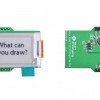
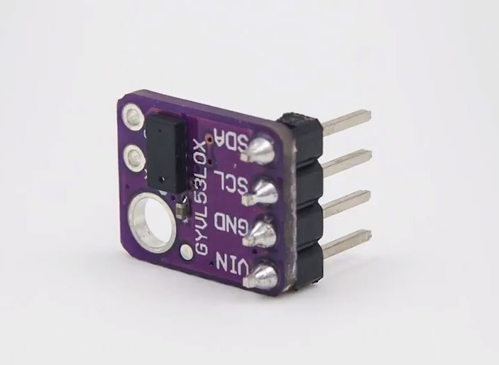
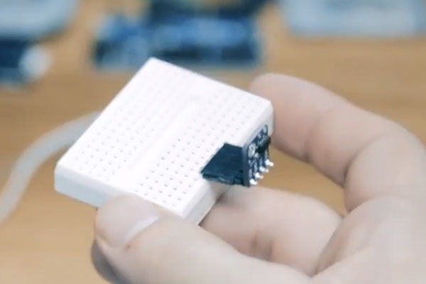
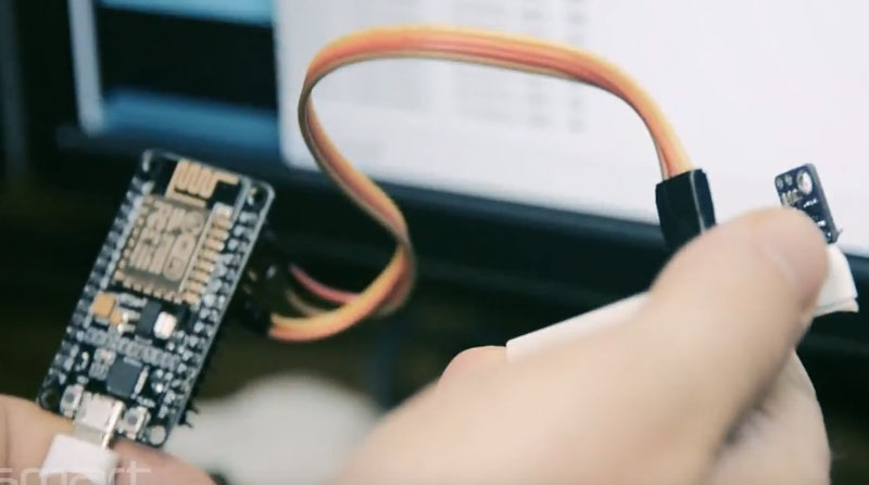
VL53L0X Time of Flight Distance Sensor
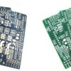
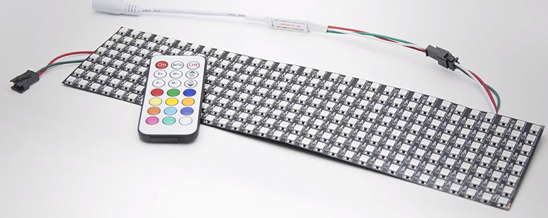
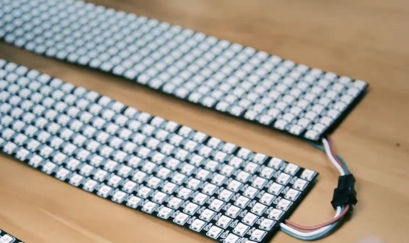
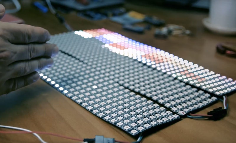
WS2812B Flexible RGB LED Matrix
Electrical Tape
Let's get started
This project description assumes you already have the Arduino IDE and necessary board definitions installed.
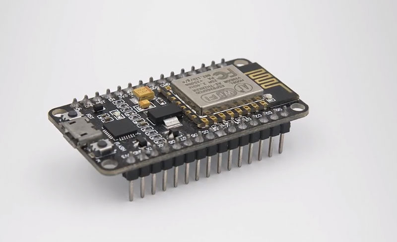
1. Get an Arduino-compatible microcontroller that can drive 768 WS2812 LEDs. In this tutorial, we used a NodeMCU with ESP8266.
2. Download and install the Adafruit_NeoPixel, Adafruit_NeoMatrix, and Adafruit_GFX libraries.
3. Download our Arduino sketch from https://github.com/NoahNOA/SP-Bricks/
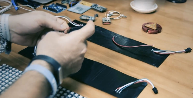
4. Take three of our flexible WS2812 LED panels and chain them together. To prevent a short circuit, put electrical tape over each of the contacts on the center wire harness on each panel, or remove (desolder) the center wire harnesses altogether. Solder a 1000µF capacitor between power and ground on the connector through which you’re supplying power. I didn’t do this in the video, but it’s definitely best practice. See Adafruit’s Neopixel Uberguide.
(If you’re powering the panels individually, desolder the 5V leads from the wire harnesses at either end of the panels. Leave the GND leads connected. Power the panels through the middle harnesses.)
The first panel should be positioned at the top with the input wire harness on the left.
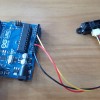
5. Connect your VL53L0X breakout board’s SDA and SCL pins to the SDA and SCL pins on your microcontroller board. In the case of the NodeMCU, the default pins are D1 (SCL) and D2 (SDA). Connect GND and VIN to the appropriate pins on.
Note that while the VL53L0X breakout that we carry is 5v tolerant on both the supply and logic pins (because it has an integrated regulator and logic-level conversion circuit), the VL53L0X is not. If you’re using a different VL53L0X board, make sure that you’re using it with a 3.3v MCU or that your board can also handle 5v.
6. Connect your microcontroller’s serial programming interface to your computer. We’re going to assume that you know how to hook up and use your microcontroller. If not, please refer to the getting started documentation associated with it. Make sure that you’ve installed the appropriate board package in the Boards Manager (Tools -> Boards -> Boards Manager).
7. Open the sketch in the Arduino IDE and upload it to the board.
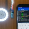
8. Open the Serial Monitor and set the speed to 115200. You should be seeing range readings from the VL53L0X. When moving your hand towards and away from the sensor aperture, you should see the value fall and climb.
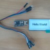
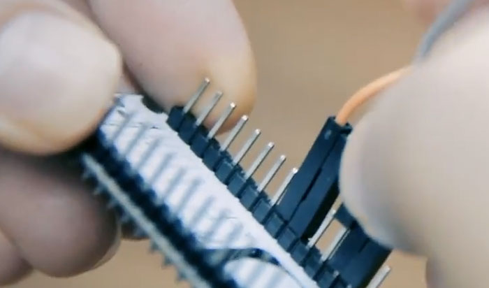
9. Connect the DIN (data in) pin from the first panel to the pin you’ve selected as your output pin for the Adafruit_NeoMatrix object in the firmware. In our case, we used Arduino Pin 0, which maps to pin D3 on the NodeMCU. Connect GND from the microcontroller to GND on the panel array. We used two female-to-male jumper wires to connect the NodeMCU’s pins to the LED panel’s input connector without a breadboard or other adapter.
10. Supply power to the LED array. This can be any 5v source that can supply enough current (See disclaimer). Make sure that the microcontroller and LEDs share a ground connection in at least one place.
11. After you've supplied power and uploaded the code, you should be seeing the array of bricks on the first (top) panel, and the paddle at the bottom.
12. Play ball!
Watch the full video here: